Based on the findings of the Environmental Impact Assessment (EIA), the LHDA drew up an Environmental Action Plan (EAP) which was divided into four parts viz. These are the Compensation (including resettlement), the Income Restoration and Rural Development, the Natural Environment and Heritage and the Public Health Plans.
The project facilitates the resettlement or relocation of persons who are affetced by the construction activities of the Project.
LHDA’s legal obligations to the people and communities affected by Project works is based on the Lesotho Constitution, the 1986 LHWP Treaty, the LHDA Order of 1986 and the LHWP Compensation Regulations, 1990: Legal Notice No. 50 of 1990.
Article 7 paragraph 18 of the Treaty on the LHWP;
The LHDA shall effect all measures to ensure that members of local communities in the Kingdom of Lesotho, who will be affected by flooding, construction works, or other similar project-related works, will be enabled to maintain a standard of living not inferior to that obtaining at the time of first disturbance: Provided that such Authority shall effect compensation for any loss to such member as a result of such project related causes, not adequately met by such measures.
Article 15 of the Treaty states;
‘The Parties agree to take all reasonable measures to ensure that the implementation, operation and maintenance of the Project are compatible with the protection of the existing quality of the environment and, in particular, shall pay due regard to the maintenance of the welfare of persons and communities immediately affected by the Project.’
The Compensation Policy that is currently in use was effective from 1st April 1998 for Phase 1A and from 31st July 1997 for Phase 1B where the Project has impacted on the capacity of the local infrastructure, The Project has compensated through construction of schools, feeder roads and community halls.
In addition to compensation for lost income and assets, the Project also includes an income restoration and rural development program to restore the productive capacity of project-affected persons so that they might benefit from new opportunities created by LHWP.
The constituent programmes include Integrated Catchment Management, Environmental Resource Conservation; and Environmental Resource Monitoring.
Integrated Catchment Management: This includes the establishment of Catchment Management Authorities, Environmental Awareness and Recycling of Waste Material).
Environmental Resource Conservation: This includes programmes such as conservation of the endangered species. One such sepcies is the Maluti Minnow (pseudobarbus quathlambae).The Maluti Minnow Project is very high profile. The Minnow is classified as a critically endangered species and the entire world distribution of the Minnow is restricted to the Lesotho Highlands.
Environmental Resource Monitoring:The water quality monitoring programme has been running smoothly since inception.
The Public Health teams were established to promote and maintain the health of communities affected by the LHWP. This was achieved through provision of health care services to the construction workforce and the local communities, creation of awareness on dangers of drug abuse, provision of adequate clinical facilities, referral and evacuation systems for the construction workforce, prevention and control of communicable diseases and provision of clean water and sanitation.
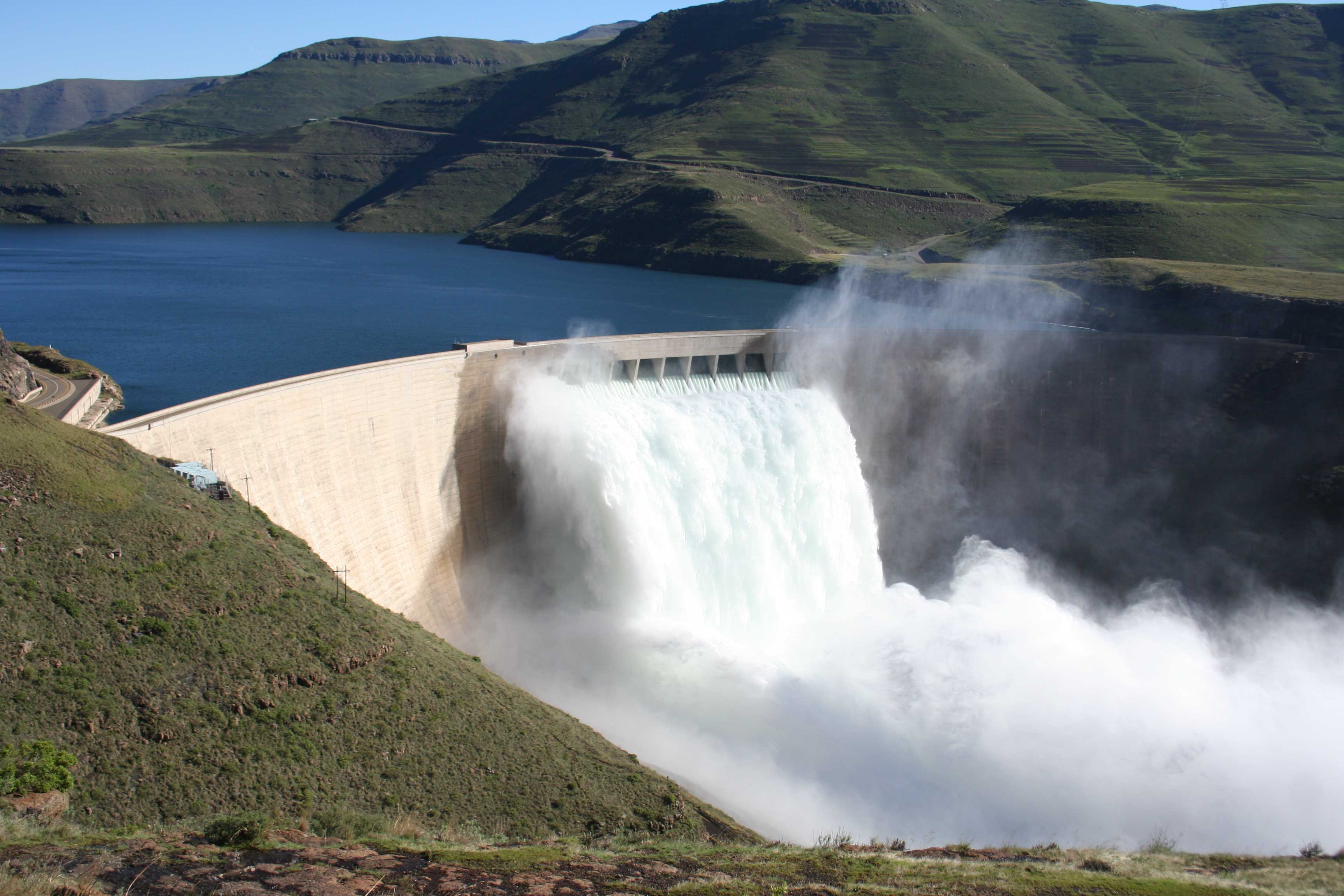
Phase 1A comprises Katse Dam, the ‘Muela Hydropower Station, ‘Muela Dam, the Transfer Tunnel and Delivery Tunnels (South and North),
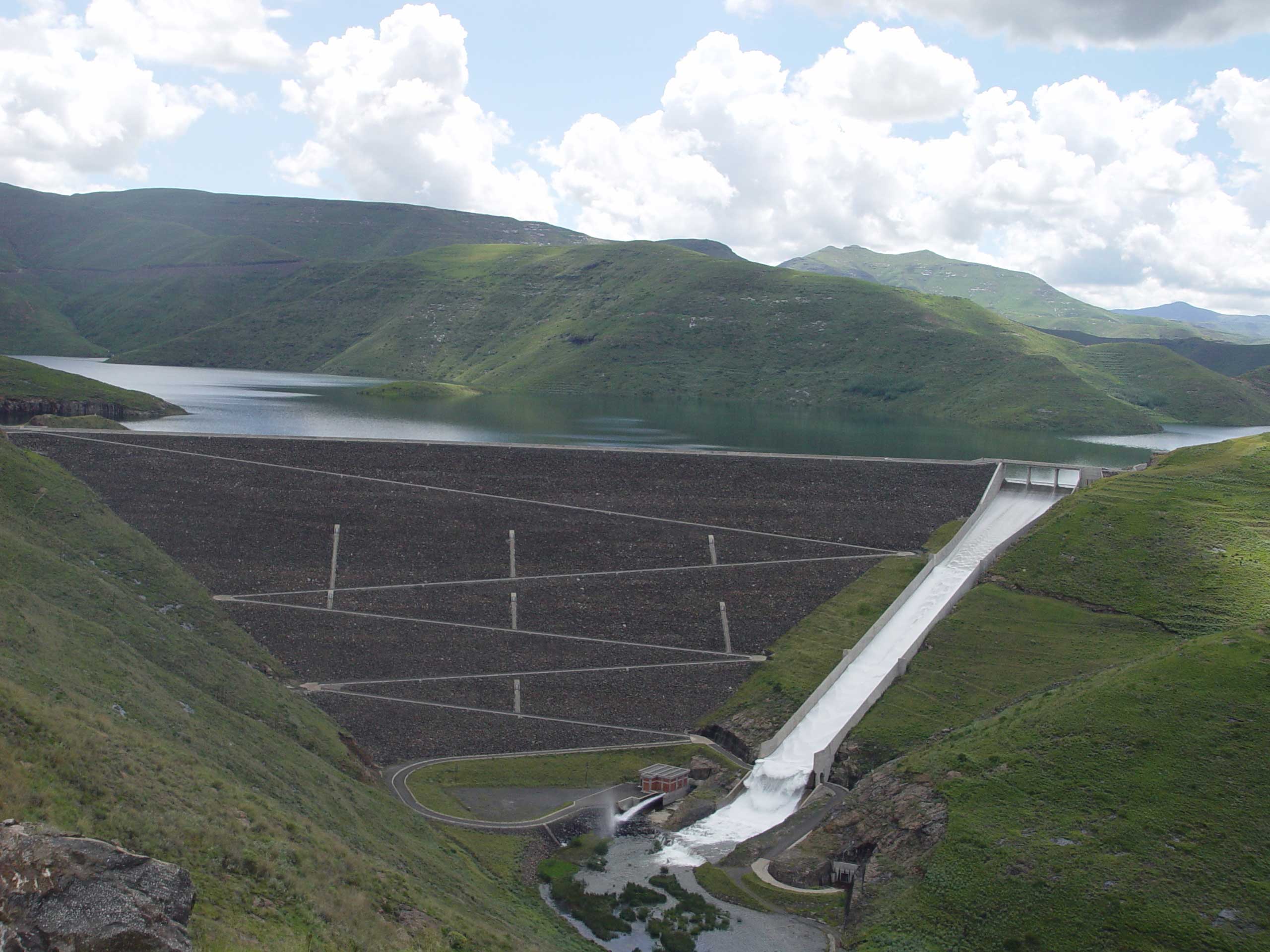
Phase 1B comprises Mohale Dam, the Interconnecting Tunnel, Matsoku Weir and the Matsoku Tunnel
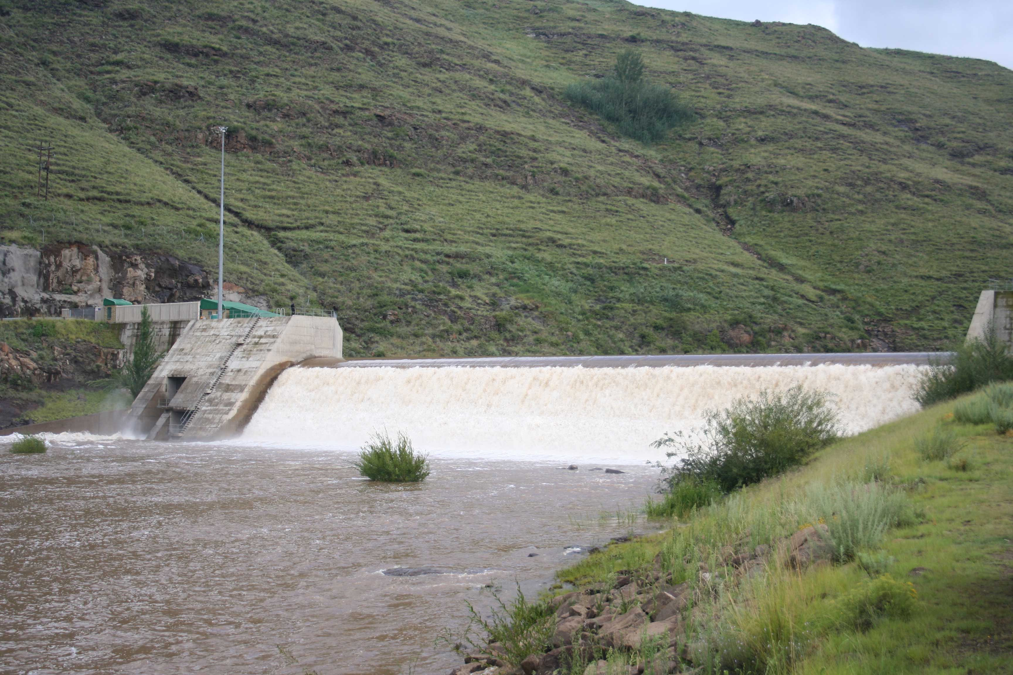
The Matsoku weir comprises a 19m high, 180m long mass concrete structure together with the adjoining electro-mechanical equipment on the Matsoku river.
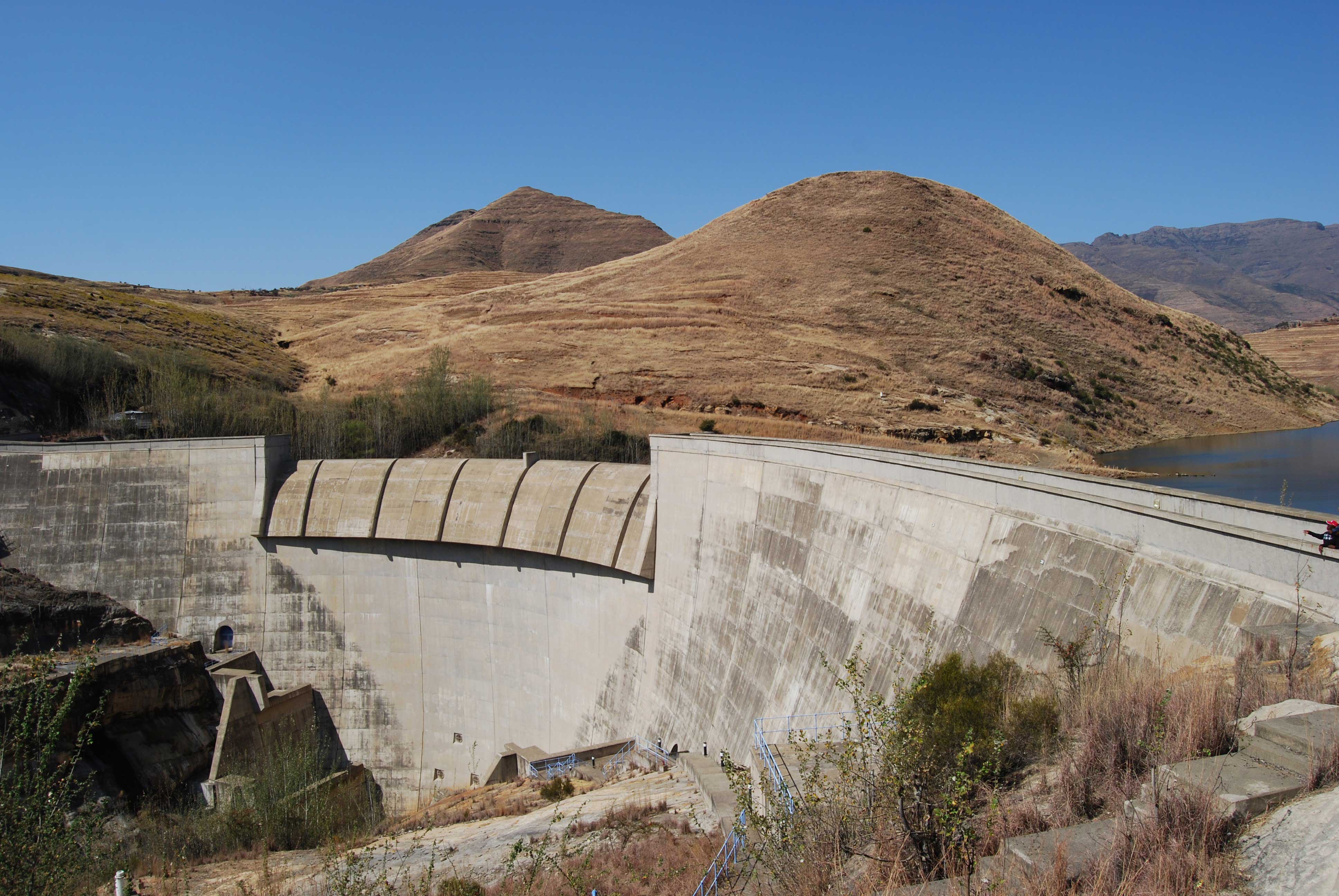
The ‘Muela hydropower station is situated mid-way between the Katse Dam in Lesotho and the Ash River Outfall in South Africa

Katse Dam is situated in the Maliba-mats’o River, three (3) kilometres downstream from where the Bokong River enters the main stream. The Dam is located in a valley between two mountains formed by basalt rock. The Dam is a double curvature arch design.
The dam was built by Highlands Water Venture (HWV), a consortium of seven international contractors namely Imbregilo (a leading company) from Italy; Bouygues from France, Hochtief from Germany, Stirling and Kier from the United Kingdom and Concor and Group 5 from South Africa. The construction of the Katse Dam started in February 1991 and was completed in May 1997.
During excavation of the dam foundation, the rock conditions prompted a conservative modification to the dam design and resulted in the incorporation of the preformed joint which is 165 metres in length at the upstream heel of the dam. The joint is designed to reduce uplift pressures and increase the effective normal load of the dam.
Basalt aggregate that was used during construction was obtained at a quarry in a neighbouring valley and moved by a 2.4 kilometre long conveyor belt passing through a 1.4 km long tunnel to the tertiary crusher which was located next to the concrete batch plant.
The dam wall has got galleries that provided access during construction and were used for joint grouting. They are now being used for reading instruments, monitoring behaviour of the dam as well as for the control of seepage water through the use of sumps and dewatering pumps.
The construction of the dam wall was preceded by the construction of a 35 metre high upstream coffer dam which diverted the water from the Malibamats’o River through two diversion tunnels. Downstream of the wall, is a tailwater dam which is 17 metres high which creates a plunge pool to dissipate the energy of the flood waters which flow over the main dam wall through the spillway.
| Height of the dam wall | 185 meters |
| Crest Length | 710 meters |
| Reservoir Surface area | 35.8 km² |
| Reservoir Volume | 1950 million m³ |
| Thickness | 60m Base & 9m Crest |
| Full Supply Level | 2053 m above seal level |
| Constructed at the confluence of Malibamats’o & Bokong Rivers | |
| Spillway Length | 150m |
| Concrete Volume | 2.4 million m³ |
| Spill way capacity | 6 252 m³/s |
| Commencement Date | 1991 |
| Completion Date | May 1997 |
| Completed | Water delivery started in January 1998 |
| Spillage Date | Early 1998 |
| Costs | 11 billion Maloti |

Mohale Dam is the second-largest dam in the Lesotho Highlands Development Project.Mohale Dam is constructed at the confluence of the Senqunyane and Likalaneng Rivers and forms part of Phase IB of the LHWP. At 145 m high, the dam is the highest concrete-faced rock fill dam in Africa. Built as a backup reserve to the Katse Dam, the two dams are connected by a tunnel that ensures there’s enough water to meet South Africa’s ever-increasing demand. At 145 m, Mohale is the highest concrete-faced rock-filled dam in Africa. An entire mountain was crushed and moved to build the rock wall. Driving in from Maseru, once again marvel at the beauty of the three mountain passes before arriving at the Dam. The drive from Mohale to Katse via Thaba-Tseka is one of the finest Lesotho has to offer. Admire the reflections of the clouds as one drives around the lake on 4×4 roads. Enjoy the visitors centre’ and Mohale Village where there is a Dam wall tour several times a day.
In contrast to Katse’s complicated structure, the construction of Mohale Dam worked on a simple principle: a mass rock compacted across a valley to form a reservoir, sealed by a concrete slab.
A large basalt hill inside the dam basin was crushed to provide the material required for this engineering feat.
| Height of the Dam Wall | 145m |
| Crest Length | 500m |
| Reservoir Volume | 946.9 million m³ |
| Reservoir Area | 21.2 Km² |
| Full Supply level | 2075 metres above sea level |
| Constructed at the confluence of Senqunyane and Likalaneng rivers | |
| Commencement Date | 26 March 1998 |
| Completion Date | 5 April 2002 |
| Date of impoundment | 1 November 2002 |
| Spillage Date | 14 February, 2006 |
| Costs | 6.5 billion Maloti |
The Matsoku weir comprises a 19m high, 180m long mass concrete structure together with the adjoining electro-mechanical equipment on the Matsoku river. This weir will divert flood waters through a tunnel into the Katse reservoir at Kutu-Kutu.
| Matsoku Weir | 20m high weir 2 cubic metres per second yield |
| Contract signed | 17 December 1997 |
| Commencement of construction | 2 February 1998 |
| Inauguration date | 26 October 2001 |
| Costs | 241 million Maloti |
| Contractors | Matsoku Civil Contractors (MCC) a joint venture of Hotchief AG of Germany Impregilo S.p.A of Italy Concor Holdings of RSA |

The ‘Muela Hydropower Station is situated mid-way between the Katse Dam in Lesotho and the Ash River Outfall in South Africa. The water enroute to South Africa uses three Francis Turbines that are installed in the powerhouse to generate 72 megawatts of electricity for domestic and export purposes.
Before the station was built, Lesotho was 100% dependent on South Africa for electricity.
After generation of electricity, water exits from the three (3) 24MW turbines into the ‘Muela Tailpond, a 55 metre high dam which provides the headwater for the continuation of water delivery to South Africa. This dam has an intake tower which first takes water into the Delivery Tunnel South which is connected with the Delivery Tunnel North for delivery to the Ash River Outfall at Clarens in South Africa.
Water from the ‘Muela reservoir can be released into the Little Caledon River through two outlet valves. The Little Caledon bypass allows water to be diverted down the Caledon River to supply emergency water to the Eastern, Central and Southern Free State, as well as Lesotho border towns during severe drought conditions.
| Dam Type | Double Curvature Concrete Arch |
| Maximum height above foundation | 55m high |
| Base thickness | 15 meters |
| Crest length | 200 meters |
| Concrete Volume | 65,000 cubic meters |
| Reservoir Volume | 6 million cubic meters |
| Spillway Crest Length | 6 million cubic meters |
| Capacity of spillway | 584 m³ per second |
Water enters this 45km-long tunnel through the operating gates of the 98m-high Intake Tower, of which only the access bridge, platform deck and operating room remain above the surface level of the waters of Katse Dam, within sight of the Malibamatso bridge. The tower has intake 'windows' at four different levels below the surface, so that the best quality water can be transferred, depending on the level of the reservoir.
The original plans for the transfer tunnel required a minimum of 6km of the structure's length to be lined with concrete, for structural support. Instability in the exposed basalt convinced the engineers that lining the full 45km of the Tunnel with 300mm thick concrete would be a safer, if more expensive option. The lining was completed by late 1996.
This 4.5m diameter, 32km long tunnel links the two major Phase 1 reservoirs, allowing water to flow in either direction, and keeping each dam at optimum operating level.
The delivery tunnel is made up of two sections: the Delivery Tunnel South, from the 'Muela power station to the Lesotho- South Africa border, and the Delivery Tunnel North, from the border to the Ash River Outfall in South Africa.
Construction of the Delivery Tunnel South went smoothly. The 15km tunnel boring machine (TBM) excavation was completed 20 months ahead of schedule, realising a saving of M85,7 million on the original R421,6 million contract. Included in the structure are two steel-lined sections that form the crossings under three rivers. Under the Ngoajane River is an l8m section of pipe housing the flow meters that measure the volume of water delivered from Lesotho to South Africa. This part o(the tunnel was the first part of Phase lA to be completed.
The 22km-long Delivery Tunnel North was also completed ahead of time (by three months) and under budget (a R52 million saving). Only one TBM was used, with the tunnel being lined concurrently with precast concrete segments, thus saving time. The first section of the tunnel, under the Caledon River (the South Africa-Lesotho border) was constructed using traditional drill-and-blast techniques, and is steel-lined.
Another means of increasing Katse reservoir's supply level and the efficient transfer of water to South Africa, the Matsoku Weir and Tunnel, will divert a maximum of 55m3/sec into the dam, so increasing the yield delivered to South Africa by a maximum of 2,2m3/sec.
A base flow of 600 litres/sec will continue down the river at all times, with water only being diverted during periods of peak flow. It is expected to be in operation by the second half of 2001.
The Matsoku Tunnel is 5,6km long, and is being constructed using drill-and-blast techniques to maximise employment for local Basotho labour. It is being lined with 75mm thick steel-fibre reinforced shotcrete. A slight downhill gradient towards Katse ensures that the facility will be gravity-fed.
The weir, 180m long and 20m high, is a solid mass (21 000m3) of concrete. Water is directed by an in-stream ledge towards a fore-bay on the left side of the weir (on picture above). Here, the base flow passes through while the excess water enters the tunnel.
The weir's downstream face features a series of large steps, designed to dissipate the energy of water overflowing the weir.
The construction contract was due to be completed by April 2001.
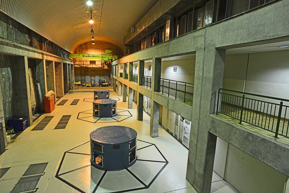
The hydropower plant at ‘Muela, in the northern Botha-Bothe District, was constructed as part of Phase 1A of the LHWP. The major benefit now derived from ‘Muela Hydropower Station is that Lesotho generates her own electricity needs.
Technically, the station consists of the 60m x 1.30m x 15m underground power house cavern that accommodates three transformers, and three turbine generators rated at 24 Mega Watts (MW) each. The Station is fed water by the Katse Reservoir via a 45km-long concrete lined transfer tunnel measuring 4.35 metres in diameter.
On the surface, there is the Operations Building that houses the control room to monitor and operate the ‘Muela Hydropower Station.The building also houses operations and maintenance staff offices and workshops.
Basically, the power generation process is effected via water that passes through the hydraulic turbines as the prime mover for the generators. Water is then discharged through the draft tubes and concrete lined connection tunnels into a 40 metres high downstream surge chamber and through 1.7km long tailrace tunnel into ‘Muela Reservoir. From the reservoir, water is conveyed by delivery tunnels via ‘Muela Intake Structure to the tunnel outlet at Ash River in South Africa. From the Ash River water flows into the Wildge River and then to the Vaal River.
| Hydropower delivery | January 1999 |
| Intake for delivery tunnel |